Strain Wave Gearbox R&D
Husky Robotics - Mars Rover Team

As part of a summer R&D project for Husky Robotics I worked with two other engineering students to design, manufacture, and test a strain wave gearbox (also known by the brand name Harmonic Drive). Strain wave gearboxes are known for there low backlash and high gear reductions, both of which are important characteristics for our rover's robotic arm. Our goal was to develop and test a functional prototype in order to investigate the possibility of integrating strain wave actuators into future robotic arm designs.
A strain wave gearbox, is made up of a circular spline, flex spline, and wave generator. The circular spline is a rigid and stationary piece, which has gear teeth around the inner diameter. The flex spline is a flexible cup where the outer wall of the top of the cup is lined with teeth. The flex spline is designed to deform into an elliptical shape under the pressure of the wave generator. The wave generator rotates around the interior of the flex spline pushing the exterior teeth of the flex spline into the interior teeth of the circular spline, translating a gear tooth on the flex spline over two gear teeth, opposite the direction that the wave generator rotates, for every complete rotation of the wave generator.
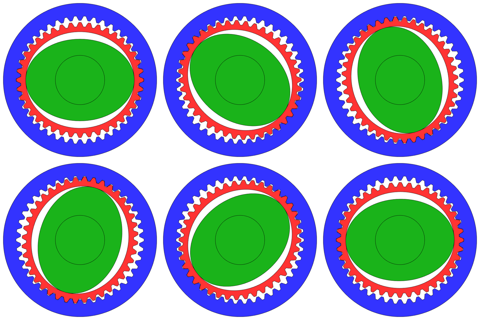
Strain wave gear animation: Circular Spline (Blue), Flex Spline (Red), and Wave Generator (Green)
After doing some background research and reading various research papers about strain wave gears/Harmonic Drives we began creating a CAD model in SolidWorks. We designed the flex spline and circular spline to be fully parametric such that we could easily change characteristics like number of teeth, pitch, pitch diameter, and tooth profile. Parts such as the flex spline and circular spline present quite a challenge to manufacture with traditional subtractive manufacturing methods so we opted to 3D print our gearbox, taking advantage of the low cost, quick turnaround time, and ability to easily achieve complex geometries.
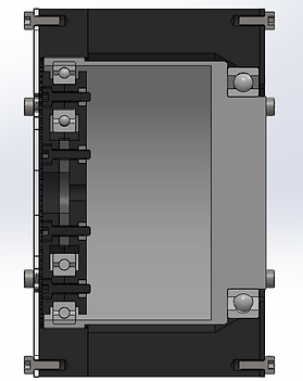
Gearbox cross section
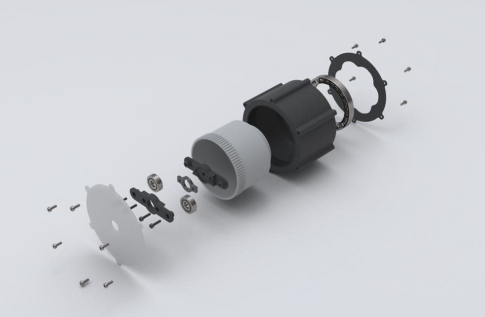
Exploded view render of gearbox
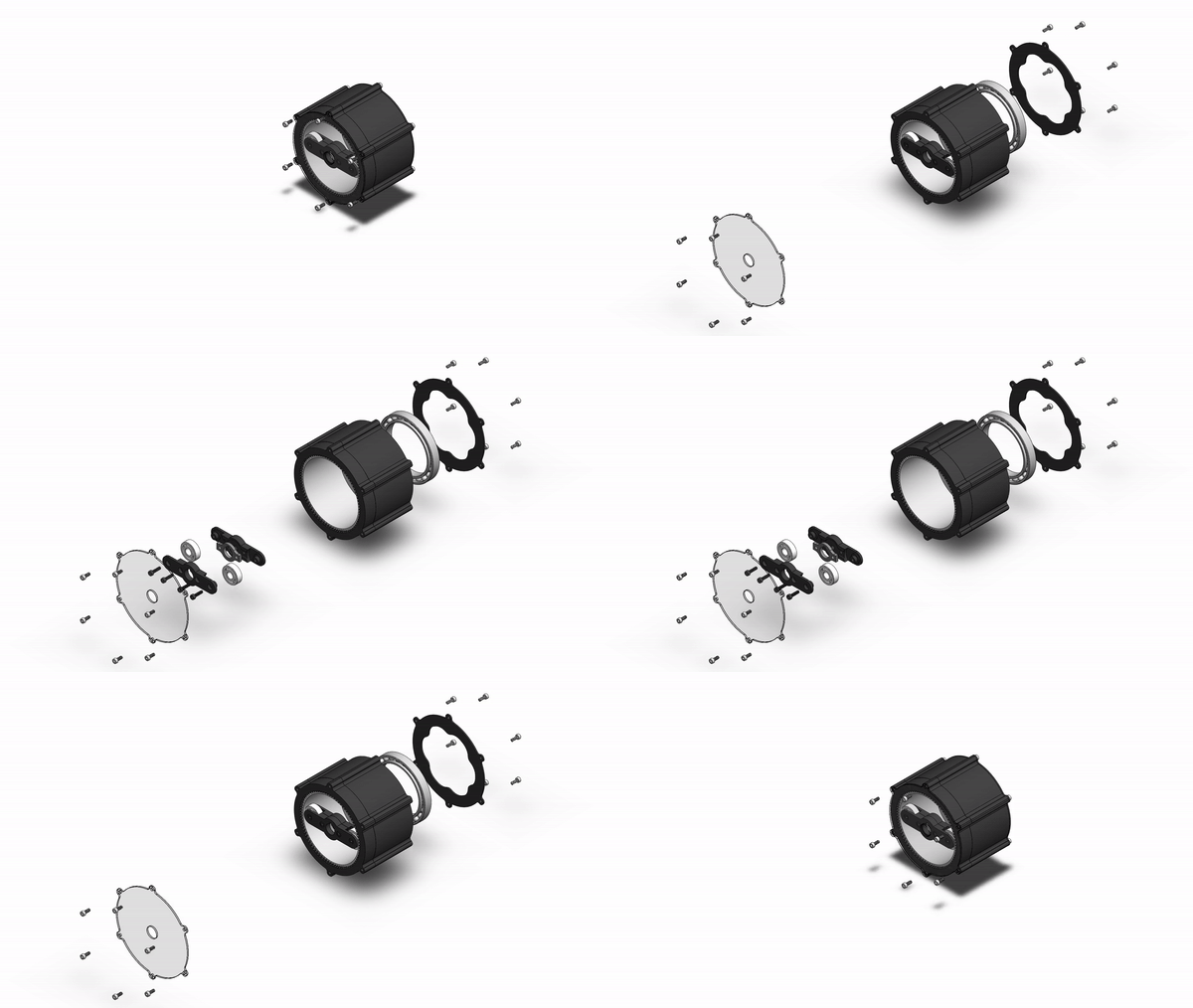
Exploded view animation
Before printing a complete prototype we first tested printing various pitches of gear teeth to determine the maximum pitch (minimum size gear teeth) of gear teeth that we could reliably print accurately. We found that we were limited to a pitch of 32. Once we knew the maximum pitch that we could print, we decided to decided to design our gearbox to have a reduction of 40:1. We picked 40:1 because it is close to the ratios we use for the planetary gearboxes on our current robotic arms and it kept the gearbox at a reasonable size.

We also tested out different tooth profiles for the flex spline and circular spline, including involute gear teeth, a version of Harmonic Drive's S tooth profile, and a couple profiles of our own design. We found that a modified version of the standard involute profile worked best for us, where we squared off the rounded edges creating a tooth that resembles a trapezoid.
Flexspline teeth

Flex splines and circular splines printed from various types of filament (PLA, PETG, etc.) and with a variety of tooth profiles
In order for the gearbox to work properly the flex spline must be flexible enough for the wave generator to deform it into the proper ellipse shape. In order to get the right amount of flex we tried printing the flex spline with different wall thicknesses and out of different materials. We found that a flex spline with a wall thickness of 1.4mm printed out of PETG gave us just the right amount of flex while being tough enough to withstand a large amount of cycles without cracking or de-laminating.

Replacable circular spline design
To make testing out different materials and tooth profiles easier/quicker we designed the circular spline to be replaceable such that we wouldn't need to reprint the entire circular spline + casing for each iteration. Replacement circular splines could be easily bolted on using captive nuts in the casing. In addition to allowing for more modularity, printing the circular spline separately from the casing produced better quality prints due to there being less overhangs.

Gearbox with PETG circular spline attached

Gearbox with elliptical wave generator design
Harmonics Drives typically use a wave generator consisting of an elliptical hub inside of a flexible bearing. Flexible bearings were way out of our budget so we needed to come up with a simpler design for our wave generator. We ended up with two different types of wave generators, a simple "bar" shape with two bearings (as seen in the renders above) and a design with 6 bearings in an ellipse shape. Through some quick testing we found that the ellipse shaped wave generator did a better job deforming the flex spline into the desired ellipse shape in addition to providing more rigidity.

Gearbox with elliptical wave generator
Once we had a completed prototype we began testing our gearbox. We focused on testing static torque, dynamic torque, efficiency, backlash, and backdrivability. In order to test these parameters we designed and built a testing station based on the concept of a prony brake dynamometer. Using a prony brake style dynamometer provided us a cheap and simple way of measuring dynamic torque and calculating efficiency. We measured output torque of the gearbox, as well as the torque applied back onto the motor (which we floated using bearings) with lever arms and strain gauges (connected to an amplifier). Using encoders on both the input and output shafts of the gearbox allowed us to calculate the efficiency of the gearbox as well as backlash. We connected the encoders and strain gauges to an Arduino Uno allowing us to collect and view their readings.
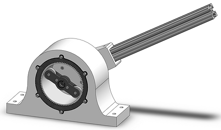
Testing jig (front view)
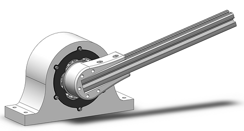
Testing jig (rear view)

Gearbox mounted in testing jig

Testing station up close

Prony brake dynamometer testing station