Robotic Shoulder Joint
Husky Robotics - Mars Rover Team

For Husky Robotics' 2022 rover I was tasked with designing the shoulder joint of the rover's robotic arm, designed to compete in the Mars Society's University Rover Challenge. The shoulder joint forms the base of our robotic arm, so it is critical that is possesses both the strength and precision to complete all mission tasks.
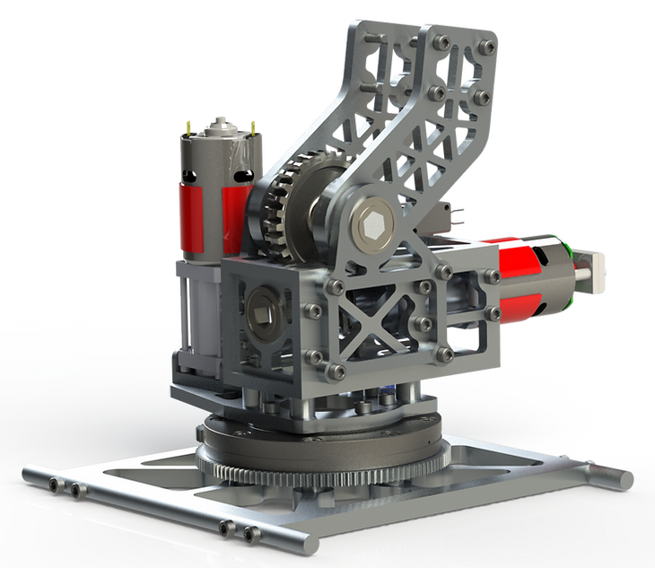
Shoulder joint assembly rendered in SolidWorks Visualize

Early stage design, calculations, planning, etc
I started by defining all the requirements for the shoulder joint. The shoulder of the arm must be able to fulfill all competition mission requirements such as lifting a 5 kg mass at full extension of the arm and dragging a 30 kg astronaut dummy. The arm must also be capable of performing precise task such as typing on a keyboard and flipping switches.
In addition to these mission requirements the base of the arm must fit within the confines of the chassis (10 in x 12in) and be able to quickly removed and replaced with the science system module. The shoulder design must also be able to manufactured with the machines in the UW student machine shop and cost no more than $500.
Next, I began looking at previous year's shoulder designs and developed a list of potential improvements and design goals. For this year's design I focused on decreasing size and weight, lowering the height of the axis of rotation (this helps lower the CoM of the entire arm), and decreasing backlash.
After brainstorming and comparing a couple of different potential designs I decided on the worm drive seen above. Before jumping into CAD I made some preliminary sketches and performed some quick calculations to determine the viability of my design.
Finally, I created a CAD model of the design using SolidWorks. I ran Finite Element Analysis (FEA) studies on all load bearings parts, and utilized topological optimization to reduce the weight while maintaining structural integrity.
Notable improvements to this year's design included replacing the previous year's axial rotation design (which used a vertical shaft and bushings) with a much more secure, reliable, and low profile slewing bearing. The planetary gearbox and worm drive is now housed within a section of box channel which also supports the plates that hold the worm gear and the bicep plates. This design helps lower the CoM of the entire arm in addition to providing a more compact and protected drive system. I was able to achieve all these improvement while reducing the weight of the assembly and increasing the strength of the joint.

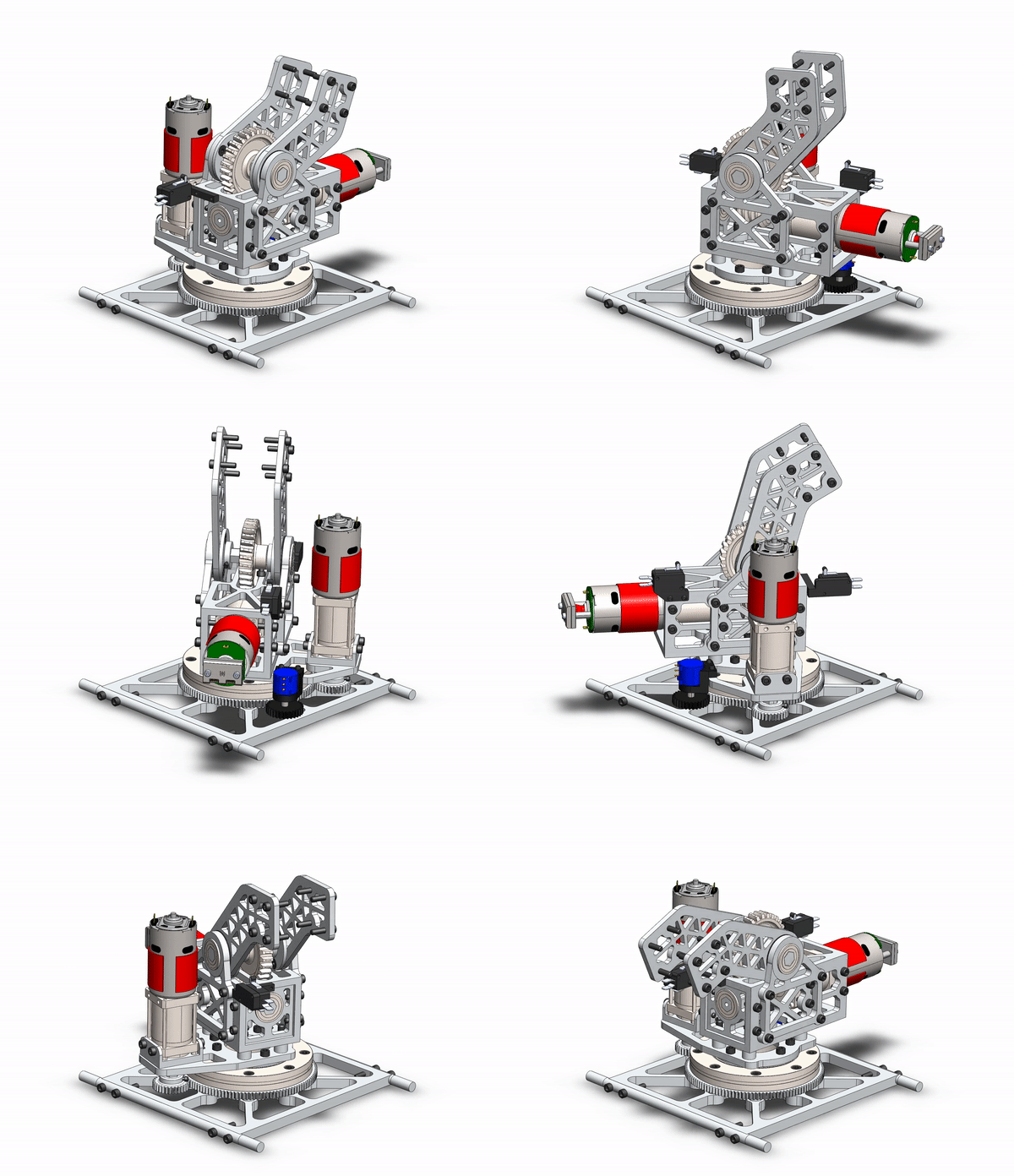
Animation of shoulder joint movement

Render of PY2023 arm
All structural components are made of 6061-T6 aluminum in order to take advantage of its specific strength (strength-to-weight ratio) and ease of machining. These aluminum parts are designed to be manufactured using a water jet, CNC mill, or manual lathe. Parts such as dust covers for the worm drive and mounts for sensors are designed to be 3D printed in order to quickly and easily achieve geometry that would be difficult or slow to manufacture using traditional methods. These parts will be printed out Nylon or PETG.

Box Channel CAD design

Machining the box channel

FEA validation

Completed part
I manufactured the metallic components for the shoulder joint in the ME machine shop using CNC milling, manual milling, manual turning, and water jetting. This was one of my first big machining projects and led me to develop an interest and passion for machining!

Milling out a bicep plate

Slew bearing interface plate

Left shoulder plate

Finished bicep plate (Different design than in renders above due to changing manufacturing method)

Chassis mounting plate

Bearing block

Partially assembled PY2023 shoulder joint

Fully assembled PY2023 shoulder joint

PY2023 arm assembled

PY2023 competing at CIRC, won 2nd place overall and 1st in Arm Dexterity