Robotic Elbow Joint
Husky Robotics - Mars Rover Team
For Husky Robotics' 2023 rover I was tasked with designing the bicep, elbow, and forearm of the rover's robotic arm, designed to compete in the Mars Society's University Rover Challenge.

Bicep, Elbow, Forearm assembly rendered in SolidWorks Visualize
I started by defining all the requirements for the elbow joint. The elbow of the arm must be able to fulfill all competition mission requirements such as lifting a 5 kg mass at full extension of the arm and dragging a 30 kg astronaut dummy. The arm must also be capable of performing precise task such as typing on a keyboard and flipping switches.
Next, I began looking at previous year's designs and developed a list of potential improvements and design goals. For this year's design I focused on increasing range of motion, mitigating backlash in the elbow joint, and reducing weight. In order to achieve these goals I decided to make two major design changes, offsetting the forearm from the bicep to increase range of motion and creating an adjustable worm drive to decrease backlash.

Assembly with wrist rotation drive shaft visible
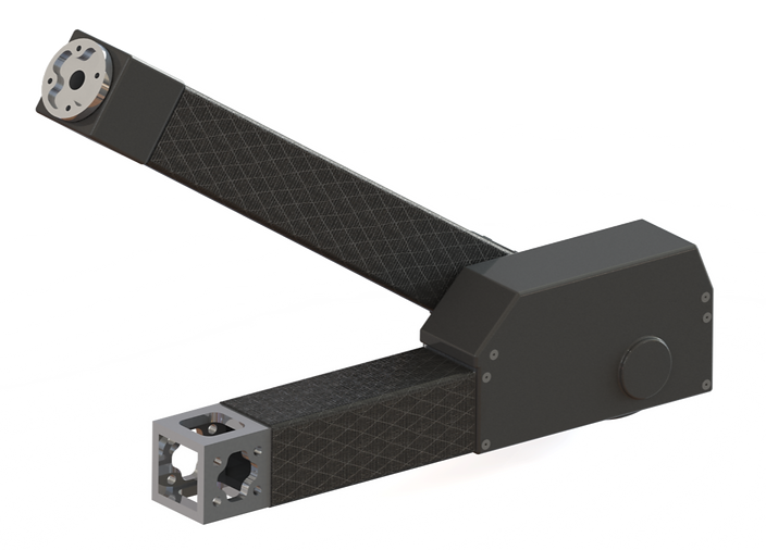
Assembly with sealed up with dust covers
Sketches of various bicep + elbow join designs


Initially I wanted all the drive components to be mounted inside the body of the bicep and forearm in order to protect them and make for a cleaner design. After sketching out a couple different potential design for the bicep + elbow joint I quickly realized driving the elbow joint internally would make the design significantly more complex and difficult to adjust. I also briefly considered using bevel gears however I quickly rejected this idea because the driven bevel gear would need to be very large in order to achieve a high enough gear ratio to achieve the desired torque. Thus I decided to only drive the forearm + wrist internally and mount the motor for the elbow joint above the bicep allowing the center to center distance of the worm drive to be adjusted.
Sketch of forearm design
Next, before making a complex CAD model I did some quick hand calculations to determine the viability of my design. My first area of concern for potential failure was the hex shaft in the elbow joint. Due to the offset joint there is a significant bending moment on the shaft as well as torsion due to the weight of the forearm, wrist, hand, and payload. In order to check for failure I analyzed the hex shaft as a beam for the combined loading condition and calculated the factor of safety.

Hex shaft calculations

My next area of concern was failure of the fasteners that attach the motor/gearbox mounting to the end cap of the bicep. When the arm is fully extended there is a large axial load on the worm which is transmitted through the gearbox and into the mounting, which creates a large shear force on the fasteners. In order to check for failure I calculated the factor of safety of the fasteners under the maximum shear load.
Fastener shear calculations
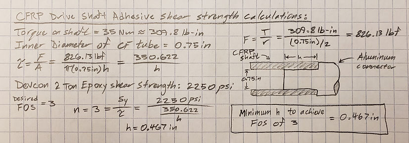
Lastly, I checked for shear failure of the adhesive that connected the gearbox output shaft coupler to to the carbon fiber drive shaft.
Adhesive shear calculations
After proving the viability of my design through hand calculations I completed a final assembly model in CAD and began running FEA studies on structural components.

FOS of gearbox/motor mounting bracket under axial load (arm fully extended)
With this new design I was able to decrease the weight of the bicep, forearm, and elbow assembly by 33%, double the rotational range of motion of the elbow joint, and add adjustability to the worm drive to decrease backlash (this will require further testing to characterize).
All structural components are made of 6061-T6 aluminum in order to take advantage of its specific strength (strength-to-weight ratio) and ease of machining. These aluminum parts are designed to be manufactured using a CNC mill, lathe, waterjet, or other common shop tools. Parts such as dust covers for the worm drive and mounts for sensors are designed to be 3D printed out of PETG in order to quickly and easily achieve geometry that would be difficult or slow to manufacture using traditional methods.
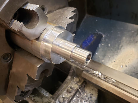
Turning wrist rotation hub
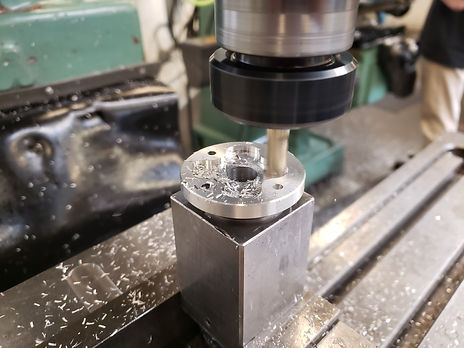
Milling wrist rotation hub pocket

Elbow bearing block
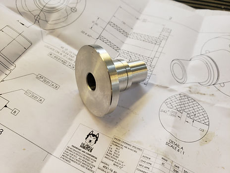
Wrist rotation hub prior to milling op
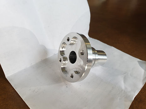
Finished wrist rotation hub
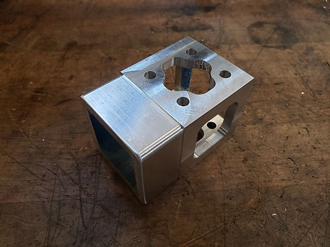
Bicep endcap

Elbow Motor/Gear Drive Housing

Elbow component ready for assembly

Partially assembled bicep + forearm